

Products Description
Technical Specs Summary
Parameter | Specification |
OEM Cross-Reference | Avago (Broadcom) HFBR-2412M (drop-in compatible) |
GIGAC Model | DT-2412M |
Function | Optical Transceiver (TX + RX — full-duplex) |
Data Rate | DC to 5 MBd (low-speed industrial control) |
Wavelength | 820nm (near-infrared LED transmitter) |
Interface | Threaded FC (industry-standard industrial connector) |
Detector | PIN photodetector |
Fiber Compatibility | 50/125μm | 62.5/125μm | 100/140μm | 200μm (all MMF) |
Power Supply | Single +5.0V |
Logic Interface | TTL (input and output) |
Protection | Conformal coating (harsh environment — moisture, dust, chemicals) |
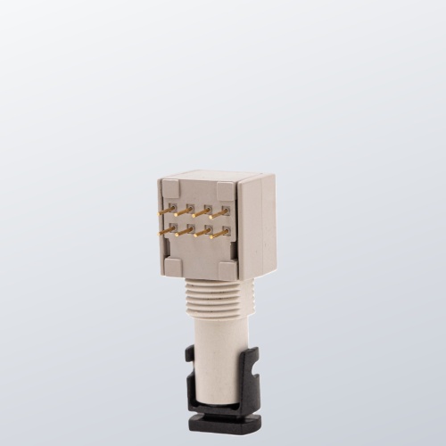
Form Factor | Miniature (compact PCB-mount) |
Mechanical Tolerance | ±0.5mm |
Applications | Industrial control links |
Detailed Product Description
Product Overview
The GIGAC DT-2412M 820nm Miniature Optical Transceiver is an industrial-grade full-duplex optical transceiver module designed as a direct compatible alternative to the Avago (Broadcom) HFBR-2412M. It offers equivalent performance and wide compatibility, operating at 820nm over multimode fiber for low-power, low-cost optical interconnect solutions in industrial control and automation environments.
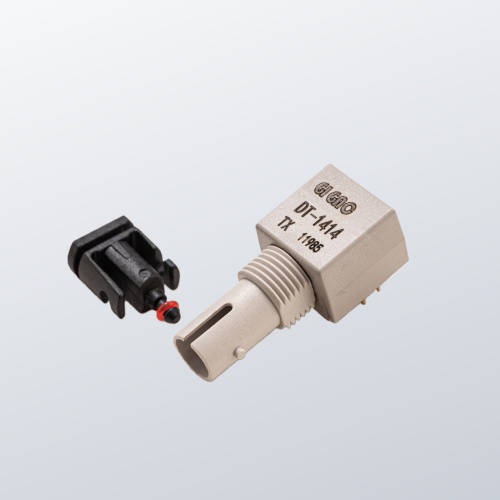
The module uses the industry-standard threaded FC connector, providing strong mechanical compatibility with a wide range of industrial equipment and simplifying device integration and replacement. Its PIN detector delivers efficient and accurate signal detection, quickly capturing and processing received signals to ensure accurate and timely data transmission. The DC to 5MBd data rate range covers the full spectrum of industrial serial communication speeds — from low-speed status monitoring to higher-speed control command links.
Powered by a single +5.0V supply with TTL logic interface, the module simplifies power supply design and reduces system complexity. The conformal coating applied to the miniature module enables reliable operation in harsh industrial environments including those subject to high temperatures, high humidity, strong electromagnetic interference, and dust — providing a solid foundation for communication in industrial control systems.
PCB TIP | PCB Design Note: When PCB wiring the DT-2412M receiver output, place an RL resistor at the receiving device pin. Adjust resistor value based on actual signal quality. This ensures signal matching and prevents signal integrity issues such as ringing and backchannel reflections, ensuring stable and reliable data transmission. |
Key Features
Full-duplex optical transceiver — TX and RX in a single compact module
DC to 5MBd data rate — covers full industrial serial speed range
820nm near-infrared LED transmitter
PIN photodetector — efficient, accurate signal reception
Threaded FC connector — industry-standard industrial interface
Compatible with four multimode fiber types: 50/125μm, 62.5/125μm, 100/140μm, 200μm
Single +5.0V power supply — simplified power design
TTL logic interface — direct compatibility with TTL industrial circuits
Conformal coating — moisture, dust, and chemical resistance
Compact miniature PCB-mount form factor
Mechanical tolerance: ±0.5mm
Drop-in compatible with Avago HFBR-2412M
Technical Advantages
Full-Duplex Transceiver in a Single Miniature Package
Unlike transmitter-only or receiver-only modules that require separate TX and RX components, the DT-2412M integrates both transmit and receive functions in a single compact module. This halves the component count per optical link on the host PCB, reduces board space requirements, simplifies routing, and lowers assembly cost — advantages that are significant in space-constrained industrial controller PCBs where multiple serial fiber links must coexist.
Threaded FC Connector — Maximum Mechanical Reliability
The threaded FC connector provides a locking mechanism that prevents unintentional fiber disconnection in environments subject to vibration, mechanical shock, and cable tension — common conditions in factory floor, motor drive cabinet, and mobile industrial equipment installations. This is a key advantage over push-pull connector types (SC, LC) in applications where connector security under mechanical stress is a requirement.
Four-Fiber Compatibility — Maximum Deployment Flexibility
Compatibility with 50/125μm, 62.5/125μm, 100/140μm, and 200μm multimode fiber means the DT-2412M can be deployed in virtually any industrial fiber plant regardless of the installed fiber type — from modern OM2/OM3 glass fiber installations to legacy HCS (100/140μm) and POF (200μm) plastic optical fiber runs that are common in older industrial facilities. This eliminates fiber type as a procurement constraint.
Conformal Coating — Industrial Environment Protection
The conformal coating applied to the module provides resistance to the moisture, dust, chemical exposure, and condensation encountered in industrial manufacturing environments. Without conformal coating, optical modules in these environments can experience corrosion of lead frame contacts, contamination of the optical interface, and PCB degradation over time. The coating is applied without compromising optical fiber coupling alignment or mechanical tolerance.
TTL Interface — Direct Industrial Control Circuit Integration
TTL (Transistor-Transistor Logic) is the dominant logic standard in legacy and current industrial PLC, DCS, and motion controller I/O circuits. The DT-2412M TTL interface connects directly to these systems without level-shifting components, reducing circuit complexity and board real estate in industrial controller designs that must interface multiple optical fiber links.
! | PCB Layout Recommendation: Place an RL (load resistor) at the receiving device pin when PCB wiring the DT-2412M output. The resistor value should be adjusted based on actual signal quality to achieve impedance matching. This prevents signal integrity problems including ringing and backchannel reflections. Refer to the application circuit diagram (Figure DT-2412M) on the datasheet for the recommended reference circuit. |
Fiber Compatibility Reference
The DT-2412M is compatible with all four of the following multimode fiber types.
Fiber Type | Core/Clad | Bandwidth | Max Distance | Typical Use |
Multimode | 50/125μm | High BW | Short | Industrial fieldbus |
Multimode | 62.5/125μm | Medium BW | Short | Standard MMF plant |
Multimode | 100/140μm | Lower BW | Medium | Legacy industrial HCS |
Multimode | 200μm | Low BW | Short | Plastic optical fiber POF |
Note: Actual maximum transmission distance depends on fiber attenuation, connector condition, and accumulated optical losses. Use the optical link budget from the product datasheet for your specific fiber type and installation.
Typical Applications
Industrial control serial link fiber optical isolation
PLC (Programmable Logic Controller) fiber I/O links
DCS (Distributed Control System) inter-unit fiber communication
Motor drive and servo controller fiber control links
Factory automation fieldbus fiber segments
Process control instrumentation fiber data links
High-EMI industrial environment fiber signal isolation
Direct Avago HFBR-2412M replacement in existing equipment
Compatibility and Deployment
The DT-2412M is a pin-compatible replacement for the Avago HFBR-2412M. It mounts directly in any PCB footprint designed for the HFBR-2412M. The threaded FC interface accepts standard FC fiber patch cords and pigtails. TTL logic connects directly to standard industrial TTL I/O circuits.
For PCB integration: place the recommended RL termination resistor at the receiver output pin as shown in the application circuit diagram. Fiber type selection (50/125μm, 62.5/125μm, 100/140μm, or 200μm) does not affect the module — specify the fiber type used in your installation only for link budget verification. Contact our technical team for datasheet, application circuit notes, or volume pricing.
FAQ Module
Q: Is the DT-2412M a direct drop-in replacement for the HFBR-2412M?
A: Yes. The GIGAC DT-2412M is pin-compatible and optically equivalent to the Avago (Broadcom) HFBR-2412M. It matches the threaded FC connector, 820nm wavelength, DC–5MBd TTL link, PIN detector, and +5.0V supply specification. It installs directly in any PCB designed for the HFBR-2412M without layout modification.
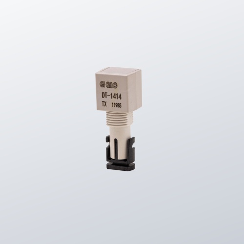
Q: What is the difference between the DT-2412M and DT-1414?
A: The DT-2412M (HFBR-2412M compatible) is a full-duplex TRANSCEIVER — it contains both a transmitter and receiver, enabling bidirectional communication through a single module. The DT-1414 (HFBR-1414 compatible) is a TRANSMITTER-ONLY module. The DT-2412M also operates at lower speeds (DC–5MBd vs 160MBd for DT-1414), uses TTL logic (vs LVPECL), and has a threaded FC connector (vs ST).
Q: What fiber types are compatible with the DT-2412M?
A: The DT-2412M is compatible with 50/125μm, 62.5/125μm, 100/140μm, and 200μm multimode fiber — covering standard glass MMF, legacy HCS (hard-clad silica), and plastic optical fiber (POF) types. This makes it deployable in virtually any industrial fiber installation regardless of the installed fiber type.
Q: What does the threaded FC connector provide compared to push-pull SC or LC?
A: The threaded FC connector locks mechanically when connected, preventing unintentional disconnection under vibration, mechanical shock, or cable tension. In factory floor and industrial cabinet environments where connectors are subject to these conditions, the threaded locking mechanism provides significantly greater connection reliability than push-pull SC or LC connectors.
Q: Why is a conformal coating important for this module?
A: Industrial environments expose PCB-mounted components to moisture, condensation, dust, and chemical contaminants that can corrode electrical contacts, contaminate optical interfaces, and degrade PCB traces over time. Conformal coating seals the module against these exposures, extending operational lifetime in harsh environments without affecting the optical fiber coupling or mechanical alignment.
Q: What is the RL resistor recommendation in the PCB design?
A: When routing the DT-2412M receiver output on PCB, place a load resistor (RL) at the receiving device input pin. The resistor provides impedance matching to the transmission line, preventing signal reflections that cause ringing and backchannel interference on TTL signal lines. Adjust the resistor value based on your specific PCB trace impedance and signal quality. Refer to the application circuit diagram in the datasheet.
Our factory
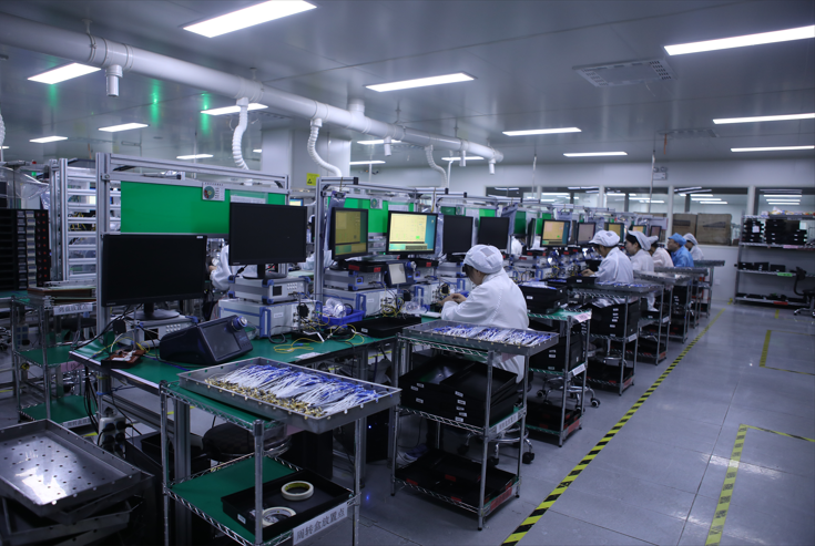
Industrial Optical Module Assembly Line
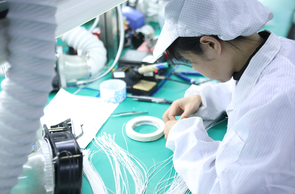
High-Precision Fiber Assembly

Automated Manufacturing for Consistency
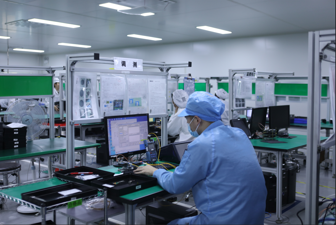
100% Functional & Reliability Testing