

Products Description
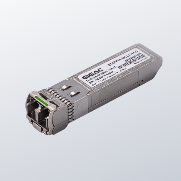
The GIGAC Dual-Line CSFP+ optical transceiver integrates two independent 1.25Gbps BiDi channels into a single compact module. Each channel supports single-fiber bidirectional transmission, reducing fiber infrastructure while enabling high-density Gigabit connectivity. With transmission distances up to 80km, DDM monitoring, and industrial temperature support, it is ideal for telecom access, FTTH, and aggregation networks.
Technical Specs Summary:
Parameter | Specification |
Data Rate | 2 × 1.25Gbps (two independent channels) |
Package | CSFP+ (Compact SFP+ — dual-channel) |
Interface | 2 × LC simplex (one per channel, BiDi) |
Fiber Type | 9/125μm Single-Mode Fiber (SMF) |
Transmission Distance | 10km / 20km / 40km / 80km (model dependent) |
Wavelength | 1310nm / 1490nm / 1550nm (BiDi pairs per model) |
Transmitter | FP / DFB laser |
Receiver | PIN photodetector |
DDM | SFF-8472 compliant — supported |
Power Supply | +3.3V single supply |
Hot Swap | Supported |
Temp. — Commercial | 0°C to +70°C |
Temp. — Industrial | -40°C to +85°C (industrial grade models) |
Standards | IEEE 802.3ah / 1000BASE-BX |
Key Features:
• 2 × 1.25Gbps independent BiDi channels
• Single-fiber transmission per channel (WDM)
• LC simplex interface ×2
• Transmission distance: up to 80km
• SFF-8472 compliant DDM monitoring
• Hot-swappable CSFP+ form factor
• Low power consumption design
• Industrial temperature option: -40°C to +85°C
• Compatible with major networking equipment
Technical Advantages:
Double Port Density in a Single Slot
The CSFP+ form factor houses two fully independent optical transceivers in the space normally occupied by one SFP. In an access switch with 48 CSFP+ slots, this translates to 96 Gigabit fiber ports — the same density that would require 96 individual SFP modules and corresponding power budget. For OLT and aggregation equipment, this halves the per-port hardware cost and slot real estate.
Per-Channel BiDi — Halves Fiber Per Link
Each of the two channels uses WDM bidirectional transmission, requiring only one fiber strand per full-duplex link rather than two. Combined with the dual-channel CSFP+ package, a single module handles four fiber directions through two simplex LC connectors — dramatically reducing fiber termination work and patch panel space in dense deployments.
Low Power Consumption for High-Density Platforms
The module is optimized for low power consumption per channel, which becomes significant at scale in high-port-count switches and OLT chassis. Lower per-port power draw reduces thermal load, allowing higher port density without exceeding power supply or cooling capacity constraints.
Per-Channel DDM for Precise Monitoring
The DDM interface (SFF-8472 compliant) provides independent real-time monitoring of TX optical power, RX optical power, temperature, supply voltage, and laser bias current for each individual channel. This per-channel visibility is critical in multi-service or multi-tenant environments where one degrading link must be isolated without affecting the other channel.
Commercial and Industrial Temperature Grades
Standard commercial-grade models operate from 0°C to +70°C, suitable for controlled data center environments. Industrial-grade variants (–40°C to +85°C) are available for outdoor access network cabinets, industrial Ethernet deployments, and other environments where temperature excursions exceed commercial specifications.
Compatibility and Deployment:
The Dual-Line CSFP+ module is designed for equipment with CSFP+ or CSFP-DD compatible slots, including high-density access switches, OLT platforms, and aggregation routers. The DDM interface is compatible with standard NMS and SNMP management platforms. Each channel operates independently — a fault on one channel does not affect the other.
For BiDi pairing: each channel's TX wavelength at the near end must match the RX wavelength at the far end of the same fiber, and vice versa. Specify the required wavelength variant and temperature grade at order time. Contact our technical team for chassis compatibility verification, paired module kits, or OEM volume configuration.
FAQ Module:
Q: What is a Dual-Line CSFP+ optical transceiver?
A: A Dual-Line CSFP+ module integrates two fully independent 1.25Gbps BiDi optical transceivers in a single CSFP+ (Compact SFP+) package. Each channel operates independently with its own TX/RX wavelength pair and DDM monitoring. This allows a single module slot to provide two Gigabit fiber links — doubling port density compared to deploying two separate SFP modules.
Q: How does a dual-channel CSFP+ differ from a standard SFP module?
A: A standard SFP provides one fiber channel. A Dual-Line CSFP+ provides two independent 1.25Gbps channels in the same slot footprint — delivering twice the fiber connectivity per slot. Each channel uses BiDi technology, meaning each link needs only one fiber strand rather than two. The result is twice the ports and half the fiber count per module position.
Q: What transmission distances are supported?
A: Models are available for 10km, 20km, 40km, and 80km over 9/125μm single-mode fiber. Select the distance variant based on your longest link requirement. Optical link budget calculations are recommended for links approaching the rated maximum distance, particularly where multiple connectors or splices are present.
Q: Do both channels share the same wavelength?
A: No — each channel has its own independent BiDi wavelength pair. Channel 1 and Channel 2 may use different wavelength combinations (e.g., 1310nm/1490nm and 1550nm/1310nm). Verify the wavelength configuration per channel from the model specifications before ordering to ensure correct far-end pairing.
Q: What temperature grades are available?
A: Commercial grade: 0°C to +70°C for controlled data center and indoor equipment room environments. Industrial grade: –40°C to +85°C for outdoor access cabinets, industrial Ethernet deployments, and environments with wide thermal variation. Specify the required grade at order time.
Q: Is this module compatible with standard SFP slots?
A: The CSFP+ module requires a CSFP+ or compatible dual-channel slot. It is not mechanically identical to a standard SFP cage, although the electrical interface follows the SFP+ standard. Verify CSFP+ slot availability and mechanical compatibility with your specific switch or OLT chassis before ordering.
Table 1 — Absolute Maximum Ratings
Parameter | Symbol | Min. | Typ. | Max. | Unit | Note |
Storage Temperature | Ts | -40 | 85 | ºC | ||
Relative Humidity | RH | 5 | 95 | % | ||
Power Supply Voltage | VCC | -0.5 | 4 | V | ||
Signal Input Voltage | -0.3 | Vcc+0.3 | V | |||
Receiver Damage Threshold | 3 | dBm |
Table 2 — Recommended Operating Conditions
Parameter | Symbol | Min. | Typ. | Max. | Unit | Note |
Case Operating Temperature | Tcase | 0 | 70 | ºC | ||
Power Supply Voltage | VCC | 3.15 | 3.3 | 3.45 | V | |
Power Supply Current | ICC | 160 | mA | @25°C (case) | ||
Power Supply Current | ICC | 180 | mA | @70°C (case) | ||
Power Supply Noise Rejection | 100 | mVp-p | 100Hz to 1MHz | |||
Data Rate | 1.25 / 1.25 | Gbps | TX Rate / RX Rate | |||
Transmission Distance | 10 | KM | ||||
Coupled Fiber | Single mode fiber | 9/125µm SMF |
Table 3 — Specification of Transmitter
Parameter | Symbol | Min. | Typ. | Max. | Unit | Note |
Average Output Power | POUT | -15 | -3 | dBm | Note (1) | |
Extinction Ratio | ER | 8 | dB | |||
Center Wavelength (GACC-3512-10D) | λC | 1260 | 1310 | 1360 | nm | GACC-3512-10D |
Center Wavelength (GACC-5312-10D) | λC | 1500 | 1550 | 1600 | nm | GACC-5312-10D |
Spectrum Width RMS | σ | 3.5 | nm | FP Laser (TX:1310nm) | ||
Side Mode Suppression Ratio | SMSR | 30 | dB | DFB Laser (TX:1550nm) | ||
Spectrum Bandwidth (-20dB) | σ | 1 | nm | DFB Laser (TX:1550nm) | ||
Transmitter OFF Output Power | POff | -45 | dBm | |||
Differential Line Input Impedance | RIN | 90 | 100 | 110 | Ohm | |
Output Eye Mask | Compliant with IEEE802.3 ah (class 1 laser safety) | Note (2) |
Note (1): Average output power measured at end of fiber.
Note (2): Output Eye Mask compliant with IEEE 802.3ah (Class 1 laser safety).
Table 4 — Specification of Receiver
Parameter | Symbol | Min. | Typ. | Max. | Unit | Note |
Input Optical Wavelength (GACC-3512-10D) | λIN | 1500 | 1550 | 1600 | nm | GACC-3512-10D |
Input Optical Wavelength (GACC-5312-10D) | λIN | 1260 | 1310 | 1360 | nm | GACC-5312-10D |
Receiver Sensitivity | PIN | -19.5 | dBm | Note (1) | ||
Input Saturation Power (Overload) | PSAT | -3 | dBm | |||
Loss Of Signal Assert | PA | -36 | dBm | |||
Loss Of Signal De-assert | PD | -22 | dBm | Note (2) | ||
LOS Hysteresis | PA-PD | 0.5 | 2 | 6 | dB |
Note (1): Receiver sensitivity at BER < 1×10⁻¹⁰ @ 1.25Gbps.
Note (2): LOS de-assert threshold; hysteresis = PA − PD.
Table 5 — Electrical Interface Characteristics
Parameter | Symbol | Min. | Typ. | Max. | Unit | Note |
— Transmitter — | ||||||
Transmitter Disable Input-High | VDISH | 2 | Vcc+0.3 | V | ||
Transmitter Disable Input-Low | VDISL | 0 | 0.8 | V | ||
Transmitter Fault Input-High | VTxFH | 2 | Vcc+0.3 | V | ||
Transmitter Fault Input-Low | VTxFL | 0 | 0.8 | V | ||
— Receiver — | ||||||
LOSS Output Voltage-High | VLOSH | 2 | Vcc+0.3 | V | LVTTL | |
LOSS Output Voltage-Low | VLOSL | 0 | 0.8 | V | LVTTL | |
Table 6 — Revision History
Version | Initiated | Reviewed | Revision History | Release Date |
A0 | Fei.Han | Sean.Lin | Initialization | 2020-10-15 |
A1 | Sean.Lin | Haiyuan.li | Updated parameter | 2024-03-21 |
Table 7 — Pin Descriptions (20-Pin Dual-Line CSFP+)
Pin | Name | Function | Notes |
1 | VEE | Transceiver Ground | VEE may be internally connected within the SFP module |
2 | TX FAULT | Transmitter Fault Indication | TX Fault is an open collector/drain output; pull up with 4.7K–10K resistor on host board. Note 1 for more information |
3 | TX1_Disable | Transmitter Disable of Ch A | Module channel A disables function |
4 | MOD-DEF2 | Two-wires Interface Data | 2-wire serial ID interface, SDA |
5 | MOD-DEF1 | Two-wires Interface Clock | 2-wire serial ID interface, SCL |
6 | TD2− | Inverted Transmit Data Input of Ch B | AC-coupled differential, 100Ω termination inside module. AC coupling inside module — not required on host board |
7 | TD2+ | Transmit Data Input of Ch B | AC-coupled differential, 100Ω termination inside module. AC coupling inside module — not required on host board |
8 | LOS1 | Loss of Signal of Ch A | Loss of Signal detected function. Note 2 for more information |
9 | RD2+ | Received Data Output of Ch B | AC-coupled 100Ω differential, terminated with 100Ω (differential) at user SERDES. AC coupling inside module |
10 | RD2− | Inverted Received Data Output of Ch B | AC-coupled 100Ω differential, terminated with 100Ω (differential) at user SERDES. AC coupling inside module |
11 | VEE | Transceiver Ground | VEE may be internally connected within the SFP module |
12 | RD1− | Inverted Received Data Output of Ch A | AC-coupled 100Ω differential, terminated with 100Ω (differential) at user SERDES. AC coupling inside module |
13 | RD1+ | Received Data Output of Ch A | AC-coupled 100Ω differential, terminated with 100Ω (differential) at user SERDES. AC coupling inside module |
14 | LOS2 | Loss of Signal of Ch B | Loss of Signal detected function. Note 2 for more information |
15 | VCCR | Receiver Power | 3.3V ±5%. Note 3 for more information |
16 | VCCT | Transmitter Power | 3.3V ±5%. Note 3 for more information |
17 | TX2_Disable | Transmitter Disable of Ch B | Module channel B disables function |
18 | TD1+ | Transmit Data Input of Ch A | AC-coupled differential, 100Ω termination inside module. AC coupling inside module — not required on host board |
19 | TD1− | Inverted Transmit Data Input of Ch A | AC-coupled differential, 100Ω termination inside module. AC coupling inside module — not required on host board |
20 | VEE | Transceiver Ground | VEE may be internally connected within the SFP module |
Note 1: When HIGH, indicates laser fault in Ch A or Ch B. Host reads Channel A/B: TX Fault from Ch A if bit 2 set in [A2H:110]; Ch B if bit 2 set in [B2H:110]. LOW = normal; output pulled to <0.8V.
Note 2: When HIGH, received optical power is below worst-case receiver sensitivity. LOW = normal; output pulled to <0.4V.
Note 3: VccT and VccR defined as 3.3V ±5% at SFP connector pin. Max supply current: 400mA @ 3.3V. Vcc may be internally connected within the SFP transceiver module.
Our factory

Industrial Optical Module Assembly Line
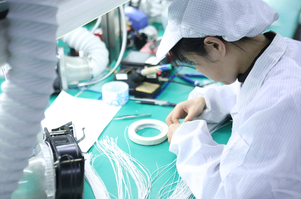
High-Precision Fiber Assembly

Automated Manufacturing for Consistency
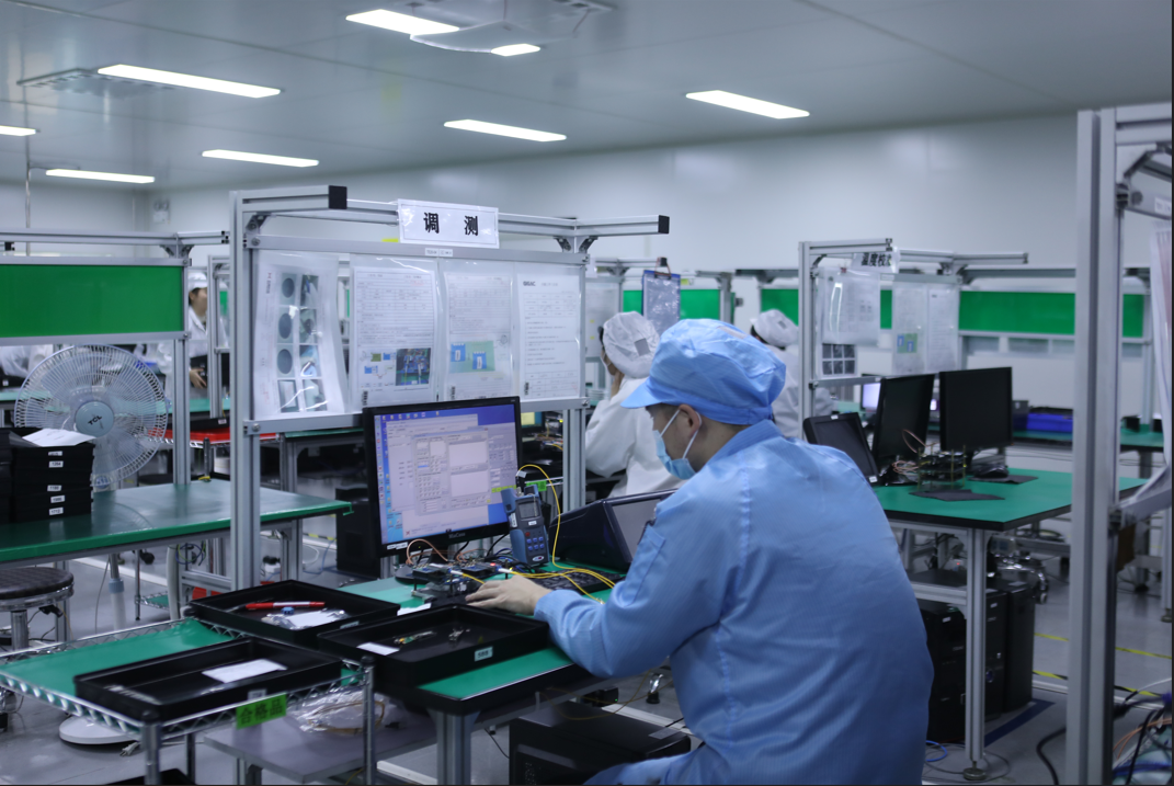
100% Functional & Reliability Testing